Gear motor selection guide: a comprehensive analysis from working principles to application scenarios
In the field of industrial automation and mechanical transmission, the geared motor serves as a core power component whose performance directly affects equipment operating efficiency and service life. Faced with a wide variety of products on the market, many engineers often encounter difficulties during selection, such as insufficient torque, excessive noise, or limited installation space. This article will start from the working principle, systematically review the key technical indicators of geared motors, and provide selection recommendations based on actual application scenarios to help you avoid common pitfalls and find the most suitable transmission solution.
Basic Structure and Working Principle of Geared Motors
Analysis of Core Components
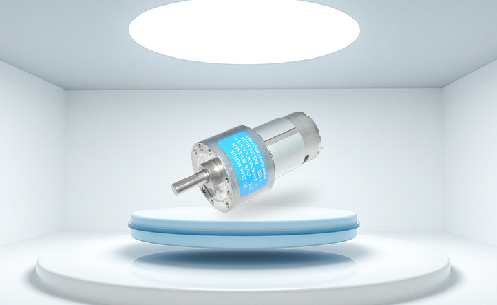
A geared motor integrates an electric motor with a gear reducer. The motor provides the original speed, while the reducer lowers the output speed and increases torque through gear pairs or worm gear pairs. Common helical gear motors use hardened tooth surfaces with transmission efficiency reaching over 95%, while worm gear motors feature self-locking characteristics, making them suitable for applications requiring reverse braking. The sealed housing is filled with lubricating grease, ensuring long-term operation without frequent maintenance.
Conversion Logic of Reduction Ratio and Torque
During selection, it is necessary to clarify the required output speed and actual load torque of the equipment. For example, if a conveyor line requires an output shaft speed of 30 RPM and the motor's rated speed is 1400 RPM, the reduction ratio is approximately 46.7. The actual torque must be multiplied by a safety factor (usually 1.2 to 1.5) to account for starting impact and overload conditions. Neglecting inertia matching may lead to motor overheating or gear pitting, shortening service life.
Three Core Selection Dimensions: Parameters, Environment, and Installation Method
Comparison Table of Key Performance Parameters
Rated power determines motor heat generation and must match the load power with a 10%-20% margin reserved. Output torque should exceed the actual load torque multiplied by the safety factor. Additionally, noise levels should be controlled below 65 decibels for office or medical environments. Protection ratings such as IP65 provide dust-tight and water-jet protection, suitable for food processing or outdoor applications. Class F insulation allows higher temperature rises, making it suitable for continuous-operation production lines.
Strategies for Special Operating Conditions
If the equipment frequently reverses direction, it is recommended to use a geared motor with a brake, whose DC brake response time is less than 0.2 seconds. For high- or low-temperature environments, temperature-resistant grease must be used and seal material compatibility confirmed. In corrosive gas environments, stainless steel output shafts or nickel-plated surfaces are recommended to prevent rust and seizure.
Comparison and Selection Recommendations for Mainstream Geared Motor Types
Helical Gear Motors: The Universal Choice for Efficient Transmission
These motors use involute gear design with high tooth surface hardness, capable of withstanding significant radial loads. Their modular design allows flexible combination of reduction ratios, covering from 3 to 200. Compared to worm gear motors, helical gear motors offer higher efficiency, saving approximately 15% of energy consumption in long-running automation equipment, though at a slightly higher cost.
Worm Gear Motors: Application Boundaries of Self-Locking Characteristics
Worm drive offers reverse self-locking capability, suitable for lifting equipment or inclined conveyors to prevent cargo from sliding after power loss. However, sliding friction results in efficiency typically below 70%, and specialized lubricating oil is required to reduce temperature rise. During selection, the continuous load rate should be calculated to avoid overheating alarms caused by prolonged full-load operation.
Application Scenario-Driven Selection Examples
Precision Positioning Requirements in Automated Assembly Lines
An automotive parts assembly line required stopping accuracy within ±0.5 mm at each station. A servo geared motor with an encoder was selected, paired with a closed-loop controller to achieve low-backlash (less than 3 arc-min) transmission. Its compact right-angle output structure saved installation space, while the IP54 protection rating adapted to workshop dust conditions, achieving two years of continuous operation without failure records.
Energy Efficiency Optimization Solutions for Logistics Conveying Equipment
For sorting conveyors operating 24 hours a day, permanent magnet synchronous geared motors were adopted, achieving IE4 efficiency standards. Through variable frequency drive speed control, the speed can be dynamically adjusted based on parcel flow, saving 30% of energy compared to traditional asynchronous motors. Their low-noise characteristics also improved the working environment for operators.
Key Points for Maintenance and Fault Diagnosis
Five Key Steps for Daily Inspection
Regularly check whether the oil level is at the center line of the sight glass, and replace the oil immediately if emulsification is observed. Listen for gear meshing sounds; metallic friction noises may indicate bearing damage. Use an infrared thermometer to check housing temperature; if it exceeds the ambient temperature by 40 degrees Celsius, inspect lubrication adequacy. Check fastening bolt torque every six months to prevent loosening from vibration. Clean dust from cooling fins to ensure natural cooling efficiency.
Rapid Diagnosis Methods for Common Faults
If the output shaft leaks oil, first check whether the oil seal lip is worn and confirm whether the breather cap is blocked. When the motor trips due to overload, use a clamp meter to measure whether the three-phase currents are balanced, and investigate whether load jamming is the cause. Unusual noise from the reducer may originate from gear pitting; stop the machine to inspect tooth surfaces and analyze iron particle content in the lubricating oil to assess wear severity.
Selecting Reliable Suppliers and Lifelong Service Support
Professional manufacturers should provide complete technical selection manuals and 3D model libraries to facilitate quick matching of installation dimensions for engineers. ISO9001 certification and CE marking are basic requirements, and a 2-year warranty with 48-hour emergency response service should also be provided. In the early stages of a project, the technical team can assist with load torque testing and issue selection calculation reports to avoid deviations caused by experience-based estimation. A comprehensive after-sales network can supply genuine parts and relubrication services, extending the full lifecycle value of the equipment.
Geared motor selection is a systematic engineering task that balances performance, cost, and reliability. It is recommended that you organize the specific operating parameters of your equipment: output speed range, load torque magnitude, installation space constraints, and ambient temperature and humidity conditions. Professional technical engineers can work with you to review calculations and recommend the optimal transmission solution. If you have upgrade or retrofit needs for existing equipment, or require customized non-standard interfaces, please feel free to contact our application engineering team for personalized technical advice and detailed product documentation.